Full step-by-step instructions on how to install a Lowrance fishfinder on a Hobie Revolution kayak. The instructions are just as relevant to other types of kayak and fishfinders.
I have already installed a side imaging sonar and a traditional 2D sonar on the fishing kayak. This installation is for a Lowrance down-imaging sonar (Elite 4 Dsi). The instructions are split into 4 main sections….
Installing and rigging for the display unit
Installing the transducer
Rigging the cables and glands
Rigging the battery
Installing and Rigging the display unit
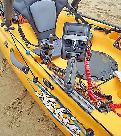
The Lowrance Elite 4 series fish finders are small and compact and ideal for use on the kayak. I would be using a Lowrance Elite 4 Dsi (down imaging) unit. The Hobie Revolution 11 has no center console, so mounting locations are limited. I wanted the fish finder to be within easy reach (so that rules out the mast bracket at the bow) and I also wanted it to be easily removable. I settled on installation on the gunwales of the Revolution using Yak Attack’s rail track. This allows a specially modified RAM ball to be slid along the track. I was also planning on using a special RAM quick release plate especially designed for the Elite 4 and 5 series fish finders.
After sitting in the Revolution 11 and seeing the lie of the land – the best location for the display unit felt like it would be on the starboard side, just above the net storage area. I taped the gear track in pace – and it all felt good.
So then to fix in the section of gear track. I offered it up to the gunwale and marked the holes with a pen…
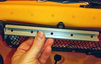
Drilled the holes using a drill bit slightly smaller than bolts…
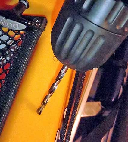
Coated the underside of the gear track with silicon sealant, and inserted the bolts…
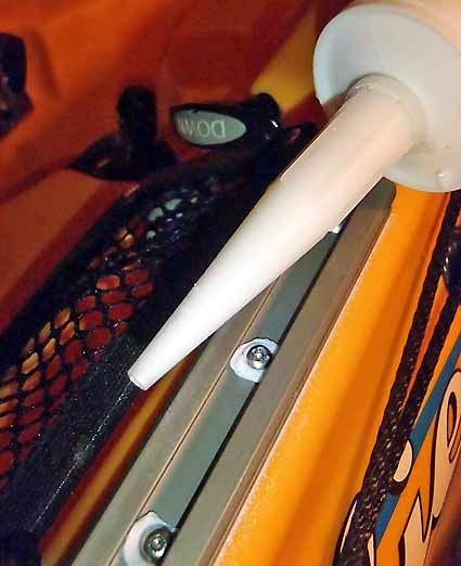
From underneath…
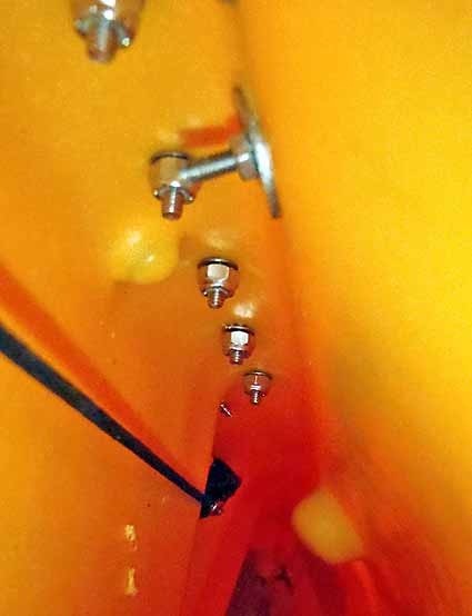
Finished gear track…
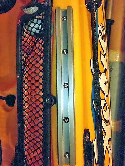
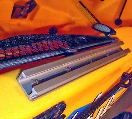
This is what the sliding Yak attack 1 inch RAM ball looks like…
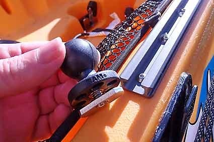
The RAM ball slides along the track and can be locked in place by twisting it.
To attach the fish finder, I used another RAM bracket together with a separate quick release plate especially designed by RAM to fit Lowrance Elite/Mark 4 and 5 fish finders (RAM-B-202U-Lo11)…
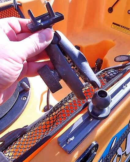
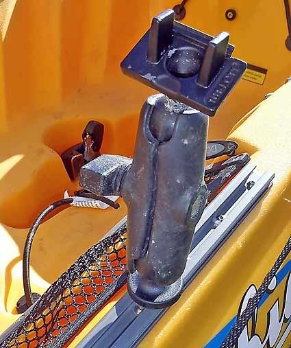
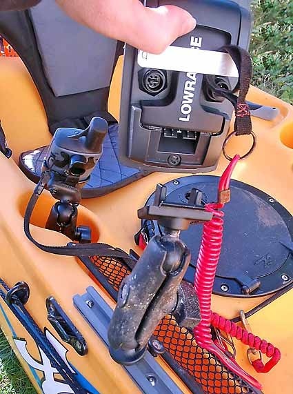
The quick release plate is a great little gizmo, and makes attaching/removing the fish finder a doddle. The fish finder simply clicks into place, and you just pull up on a sliding plate on the back of the fish finder to release it.
Installing the transducer
The best transducer signal is always going to be from a transducer mounted in the water – fact ! However, I do like the simplicity of a thru-the-hull transducer installation. There are no swinging arms, or bits sticking out of the bottom of the kayak which could be knocked. So, I have gone for a thru-the hull installation, which is quite unusual for a down-imaging sonar transducer. It requires a bit more effort, because small gains in the quality of the install, can make a big difference to the displayed signal. Down imaging transducers mounted thru-hull also have to be partially surrounded by sealant (as opposed to simply being stuck to the hull, as is the case with traditional 2D transducers).
The location of the transducer is important – you need to avoid disturbances caused by the hull, paddles, mirage drive or even motor ! The disturbances are known as cavitation, and can be caused by air bubbles in the water. For that reason, I located the transducer at a point in front of the Hobie’s mirage drive – between the mast receptacle and the mirage drive.
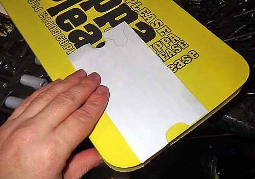
I placed a piece of paper in the hull, and cut it to the shape of the transducer cradle that I wanted to make.
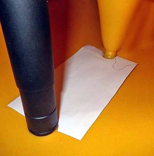
Then I used a block of high density foam (Gardeners kneeling pad – get them from garden centres)…
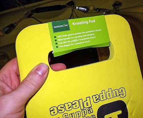
…and marked out the shape of the transducer cradle using the piece of paper…
The exact dimensions of the transducer cradle (to fit a Hobie Revolution 11) are shown in the image below (the mast holder is on the LHS and the mirage drive on the RHS)…
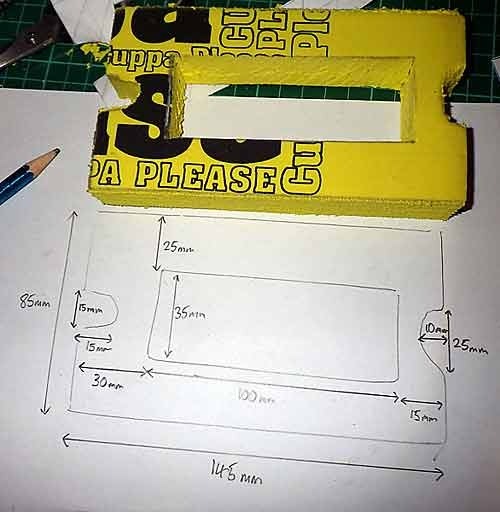
The gap in the middle is where the transducer is located. A quick dry-run to check that the transducer cradle will fit…
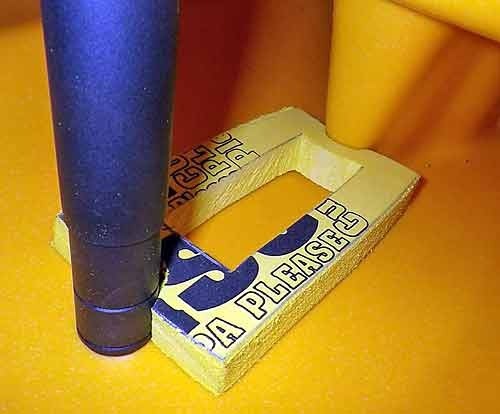
Then the cradle is fixed in place using silicon sealant…
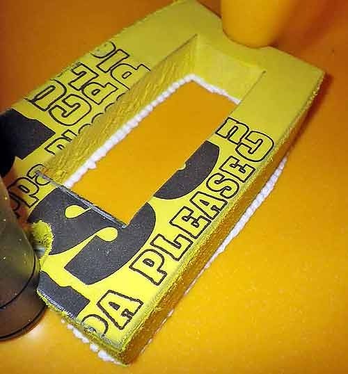
Once the sealant is dry and the cradle is fixed in place, you need to fill the gap in the middle with Sikoflex…
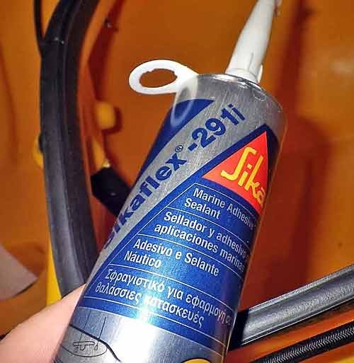
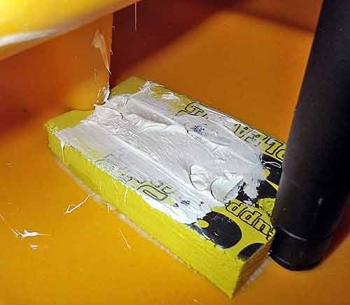
You must make sure that there are no air bubbles in the Sikoflex. I used a decorator’s filling trowel to push the Sikoflex into the cradle and remove air bubbles…
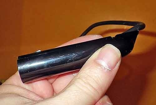
The transducer for down imaging sonar, is an unusual shape…
Press the transducer into the Sikoflex – make sure that is is facing the right way, is level (horizontally and vertically) and is pressed right down to the hull of the kayak….
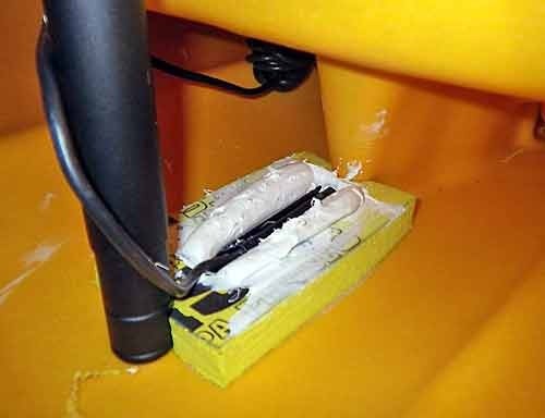
You need to allow at least a couple of days for the Sikoflex to dry and cure.
Rigging the cables and glands…
For the fishfinder to function correctly on the kayak, you need to ensure that all of the cables have waterproof connectors, and are routed through the hull of the kayak using waterproof glands.
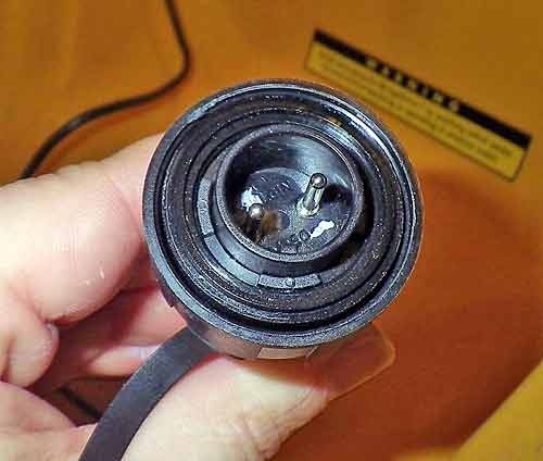
The fish finder power lead has to be connected to a power source (in our case, the 12v battery – see “rigging the battery section”). To connect to the battery, a 2 pole 12v waterproof connector is used…
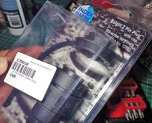
Connecting the power wire is simple; I marked the +ve and –ve poles using a pen, then simply screwed the wires into the connector and tightened the gland to make a waterproof connection (the battery has a waterproof plug which this connector fits into).
Next, the wires from the inside of the hull need to be routed through the hull and to the fish finder display unit on the outside of the hull. In order to make this connection waterproof, we use a waterproof gland. Glands allow wires with chunky or think connectors on the end, to be routed through a hole whilst still providing a waterproof membrane.
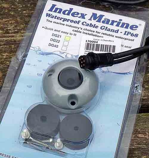
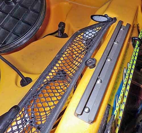
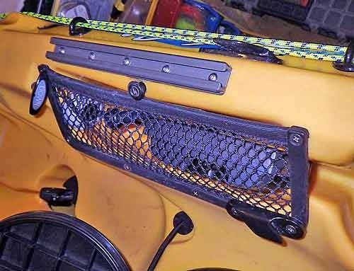
Looking at the Hobie Revolution 11, and the location of the fish finder display unit, there was an ideal location for the gland…. right on the edge of the mesh pocket on the starboard side. The self tapping screws holding the mesh together were undone…
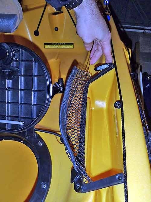
Then the main part of the gland was placed in the correct position, and the fixing positions were marked with a pen…
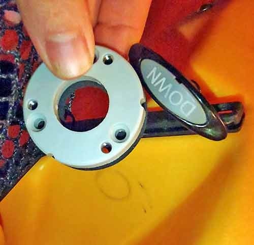
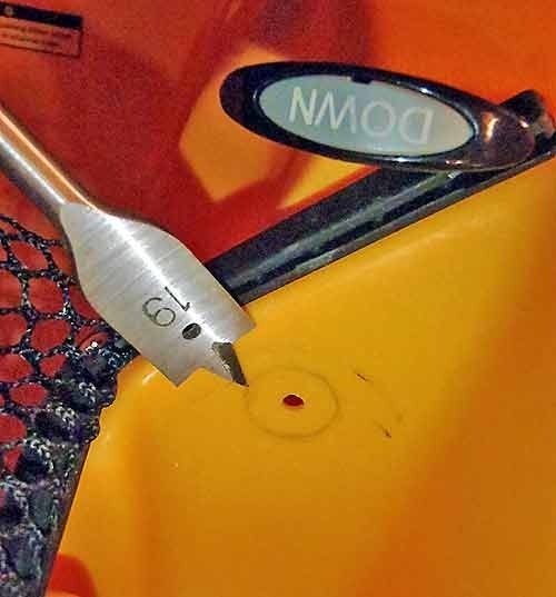
The hole was drilled with the correct sized bit…
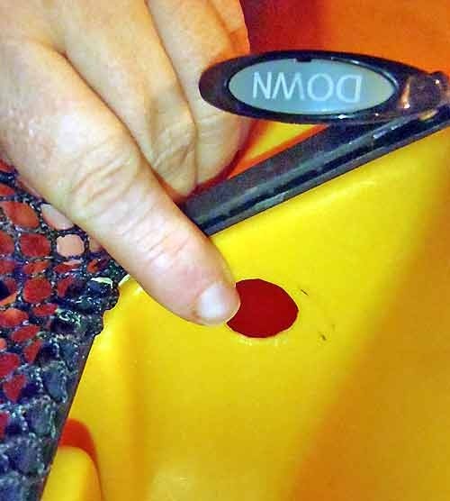
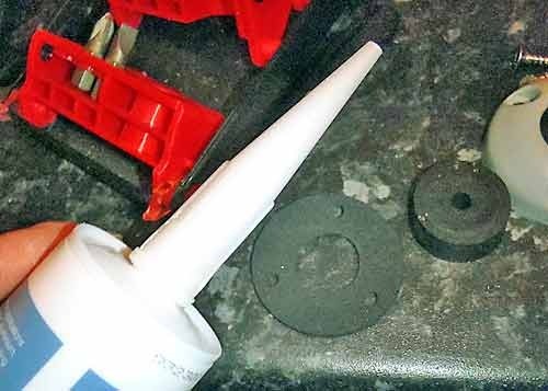
The neoprene membrane was coated with silicon sealant and the gland was attached…
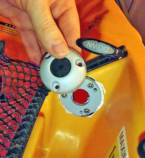
Now, with the Lowrance fishfinders, a single connector is used to supply power and transducer needs. The connector on the ends of the power/transducer lead has a collar, which is quite wide. The trick is to push the collar down the plug…
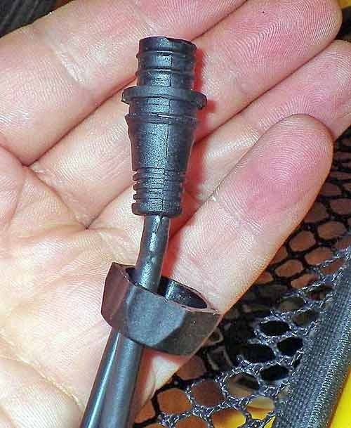
Then push the collar (and cable) through the hole first. Once the collar has been pushed through the hole, the connector can be pushed through.
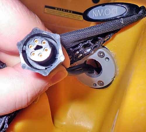
Take the rubber seal which provides the best fit (the gland I used had several different sized seals for use with different diameter cables) and insert it over the cables (the rubber seal has a split across its radius).
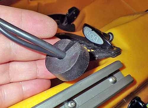
Then put the cover on the gland ad tighten everything up…
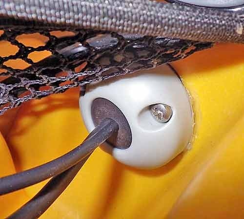
The gland provides a waterproof seal for the power and transducer cables, and the excess cable can be stowed in the mesh storage compartment when not in use – very neat.
Rigging the battery
I used to use waterproof battery boxes to house my 12v fishfinder batteries, but over the last few years, I have found that a waterproof battery bag is far more versatile.
Full instructions on how to make a waterproof battery bag can be found here.
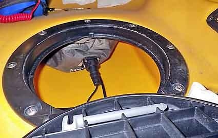
The 12v battery fits neatly into the main hatch just in front of the seat…
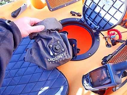
The power lead from the fish finder plugs directly into the battery bag using the same waterproof connector), and the battery can be stowed under the seat improving the centre of gravity…
The finished job
Here are some pictures of the finished job. Its a very low profile installation; the transducer, and battery are inside the hull, the external wires are hidden in the mesh side pockets, and the fish finder display unit can be slid forwards and backwards and removed in seconds.
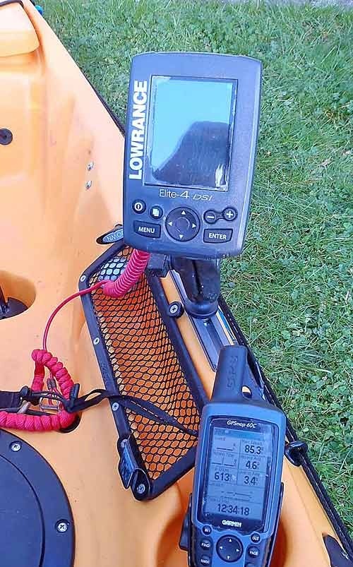
For surf entry/exit, the unit itself can be stowed in the mesh side pocket (or in the main hatch)…
For more information on Hobie kayaks, please contact the Hobie Cat centre at Poole…
http://www.hobiecatcentre.co.uk/
To order Yak Attack products, contact the UK dealer…
http://www.kayakfittings.co.uk/index.html
——————————————-
Update 30/3/13
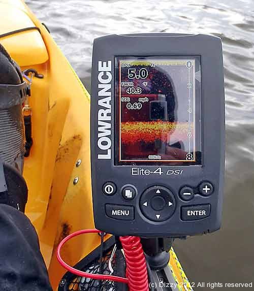
I have just come back from a chilly day at Llangorse lake surrrounded by snow covered mountains. I fished in the Llangrose Species Comp organised by Martin Hurst and Ed from SWKA. It gave me the chance to try out the fish finder… the through-the-hull installation perfromed better than I ever could have hoped. The images were clear and sharp, and I couldn’t see much noise on the display, which was my biggest concern. I have included an image from the finder (taken in only 5 feet of water). The images in the deeper water were even better – so hopefully this will re-assure alot of people who were thinking of performing a simialr thru-the-hull installation on a downimaging/DSi sonar…
Update 1/2/14
I had the transducer come away from the hull inside the kayak – on closer inspection, the Sikoflex 291 had failed, and the transducer had come unstuck (probably whilst the kayak was being transported on the car upside down – its very bumpy). I cleaned the transducer and the foam housing. Then I followed the same process as above, but used Marine Goop instead of Sikoflex 291 (ordered from Palmer metals in the UK) to attach and fill the transducer boot.
Update 16/2/15
The transducer and fishfinder with the marine goop are still going strong

